Summary of the week
This week was very interesting, because I really wanted to learn how to use laser- and vinylcutters. Reason for that is that I have such machines also in my digital learning lab, but I haven't yet used those for anything. Now after this assigment I got first touch to this category of digital fabrication
I did cut Scratch cat to be put on my classroom's door and had many other ideas which are waiting for some time to be implemented. However, I did some sticker tests in order to explore how certain vinyl cut design work when put into windows. I would like to add some vinyl stickers to my classroom
I found parametric design in Fusion360 quite difficult and it took a lot of effort to be able to design proper press-fit kit with parametric principles so that Fusion 360 didn't give a lot of errors, or warnings AND that actually I got that design than I wanted.
ASSIGNMENT 1: Cut something on the vinylcutter
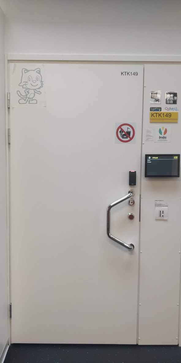
I wanted to cut something which would be useful also in my classroom. Pretty soon I decided to prepare image file of Scratch Cat. I would cut it as a vinyl sticker and put it into door of my classroom. This was nice exercise, because I did succeed with my design exactly as I did plan!
Preparing image in Inskcape
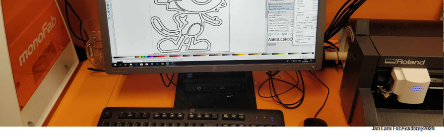
I started this assignment by searching appropriate photo about Scratch cat. When I found one, I did copy-paste it into Inkscape
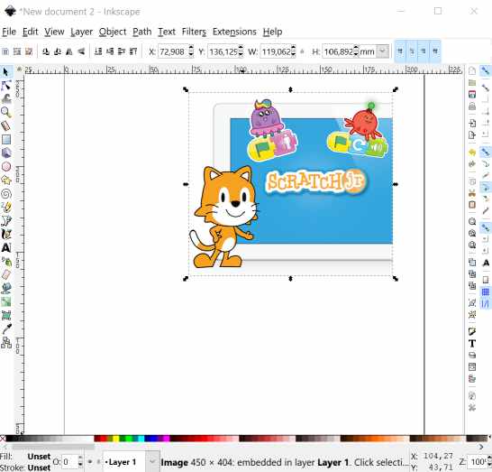
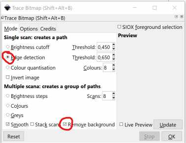
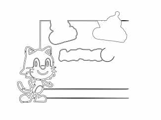
Then I did use "trace bitmap" tool to recognize edges and to remove background from the picture.
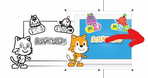
After that I did just drag bitmap image away from separated linedrawing (vector image) and continued to work with that in next step
In next space I did use "break apart" function to explode vector image to smaller segments (paths).
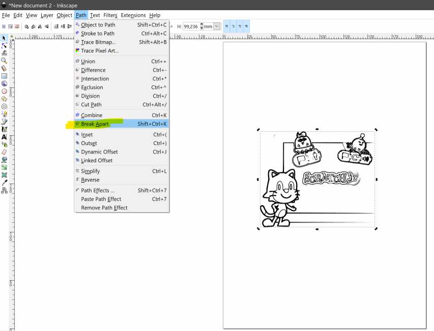
Break apart function made my vector image to totally black, so I had to open color panel and remove background color (fill color) and change stroke color to black. Also line width was adjusted in this phase
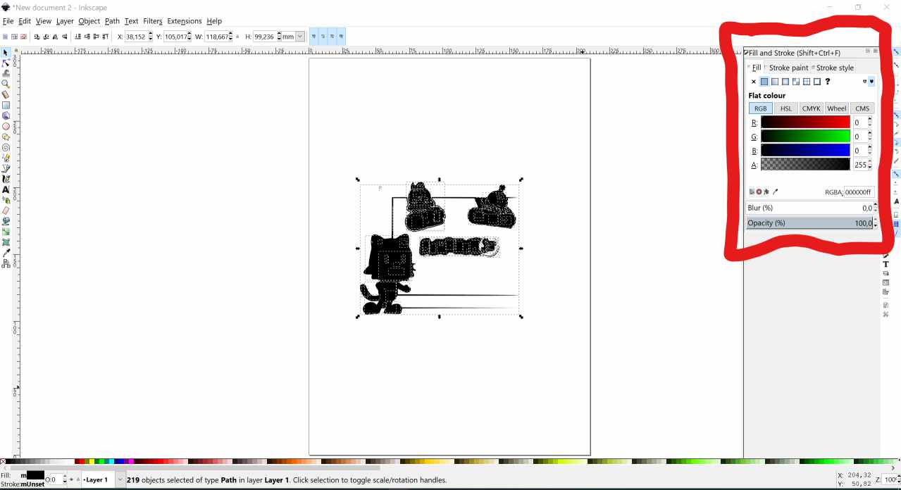
After that I got proper image, which was ready to removing unnnecessary parts of the vector image
Cutting the sticker
Then it was time copy .svg to memory stick and go to another computer which was situated next to Roland CAMM-1 GS24 vinyl cutter.
I picked up leftover of black roll from the selection of colors. Edge of vinyl is best to set close to knife to avoid usage of extra material when cutting. Pinch rollers needs to be set at edges of vinyl and on the white indicator lines.
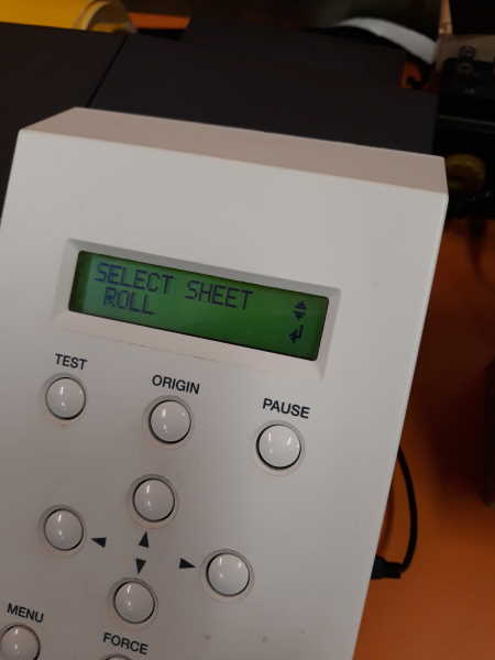
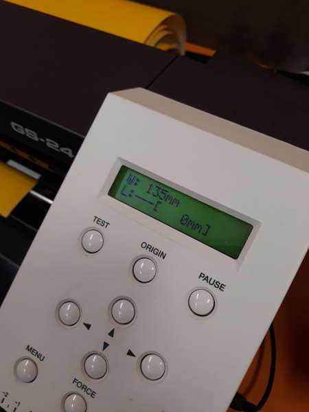
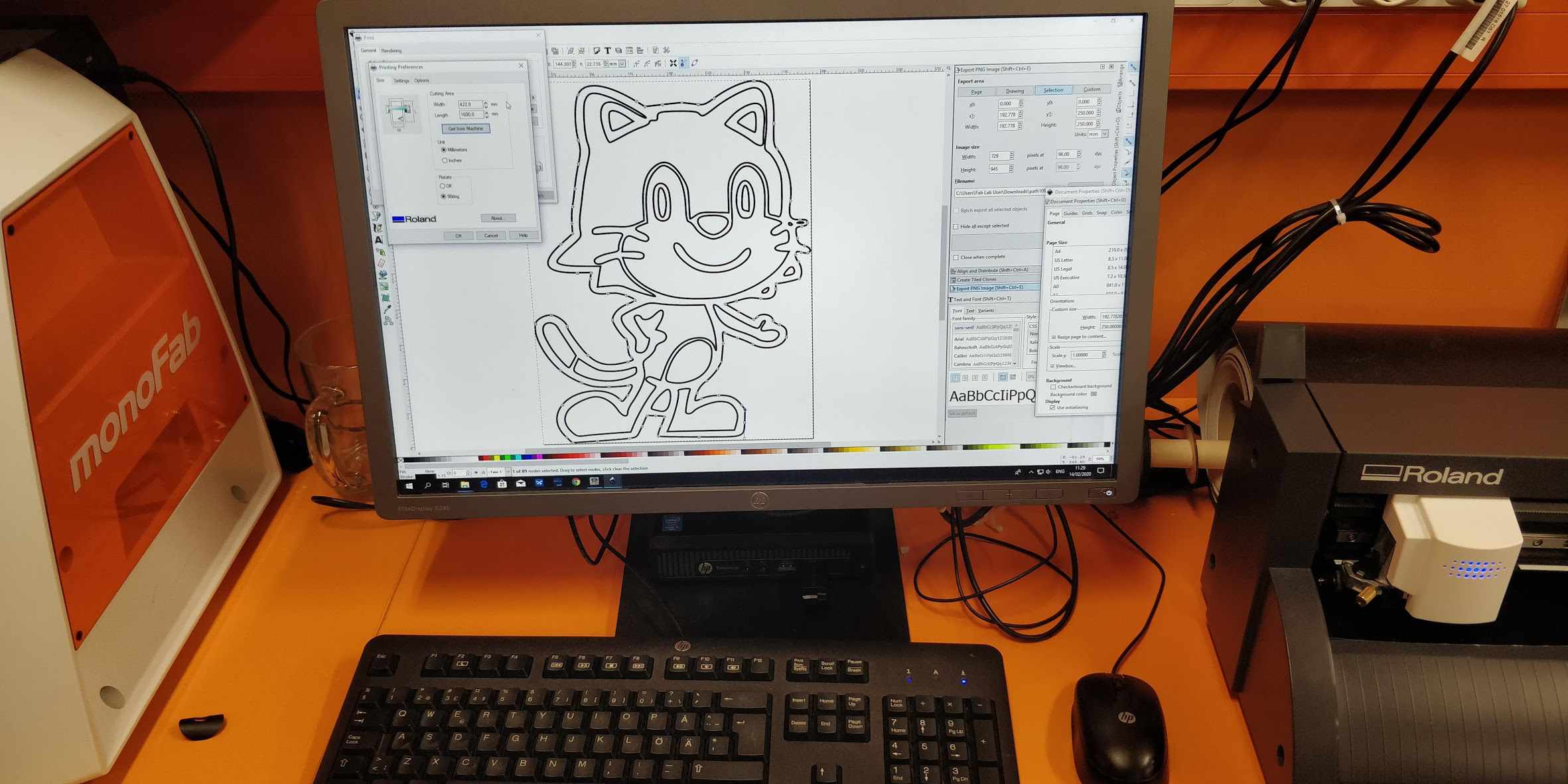
Pictures below show the userinterface of the Roland vinyl cutter. There are 3 selections available for material form: a) piece; b) roll and c) edge.
I used roll. It is not advised to use Piece option unless you have small piece and you need width AND height of the piece. After choosing this option, machine tests width and shows it on screen (second picture). This is useful since there is option in print options to get size from machine.
Then I openeded .svg image in the computer next to vinyl cutter.
I did adjust vinyl cutter so, that it was ready for cutting and then send file to the print (ctrl+p), in the printing preferences I did click "cutting area>get from machine" and then confirmed
Now I had to wait for the cutting to be ready
Finalizing the sticker: Peeling the unnecessary vinyl off
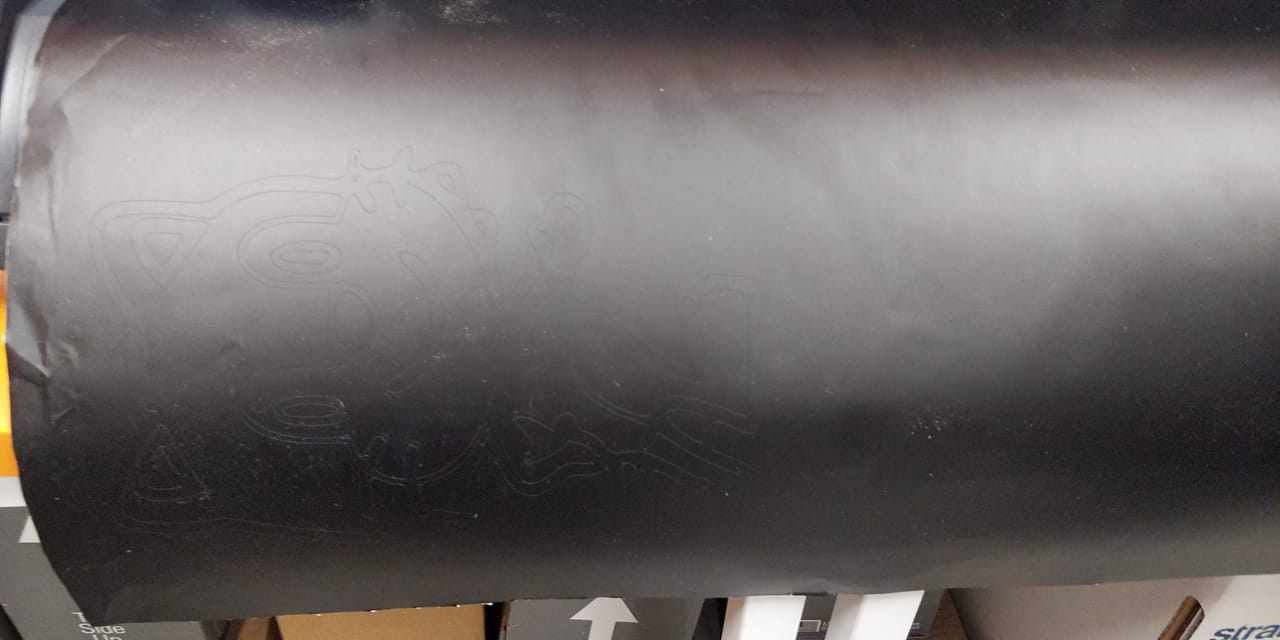
photo below shows my cat just immediately after cutting. Next step was to peel unnecessary vinyl off. Vinyl cutter does just cut traces, removing the actual sticker is not done by automatically, instead it's manual task.
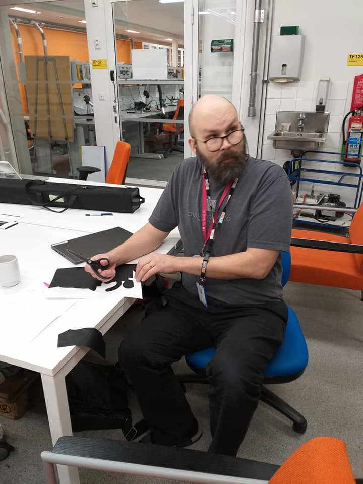
First I did cut out my sticker from the bigger roll by using scissors. Then I started to peel off extra materials. Scatch cat has some details which are pretty small, so tweezers were important tool in addition to scissors and fingers.
Because I wanted to put my stickerr to classroom door, I used temporary support sticker to help with the process
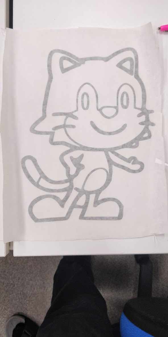
Ready!
ASSIGMENT 2: Design, lasercut, and document a parametric construction kit
In this task I had to lasercut and document parametric construction kit, accounting the lasercutter kerf. This construction kit should to be assembled multiple ways.
This was very challenging task for me, because I am just learning how to use Autodesk Fusion. Normally I would use tutorials to help me to learn, but now in parallel with this task my computer was in repairshop and I had to use few days replacement laptop without autodesk fusion
However, I did succeed to design artefact by using parametric approach, but honestly, it was very difficult to achieve :)
Anyway, I did learn idea of parametric design, which was meaning of the exercise I suppose.
First experiences of parametric design: trial and error -approach to parametric design
As I described, I had "some" issues with my parametric design efforts. I started my design by exploring student products from earlier years and found that simple design might be good starting point for very beginner.
So I decided to start with square. I did sketch it with parts aimed to be slots. I also learnt how use "points" to guide parts in their places in our local lesson. However, this was just beginning of nightmare, but I didn't knew yet it
I got stuck with my first design, so I did draw very basic shape manually by following structure of the page
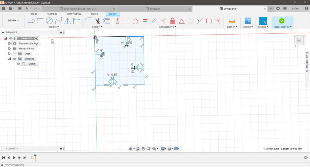
Here is my first parametered value (width of the slot) in design. I was so proud!
Issues with parametric design started to emerge
Pretty soon I noticed that behavior of my design started to be pretty weird. Picture shows how width of different sides of my square are not equal.
I tried to solve this issue by using constrains, which was also new feature for me. I partly succeeded.. but only partly..
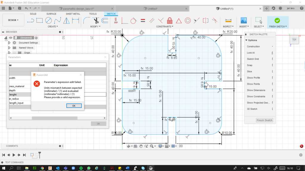
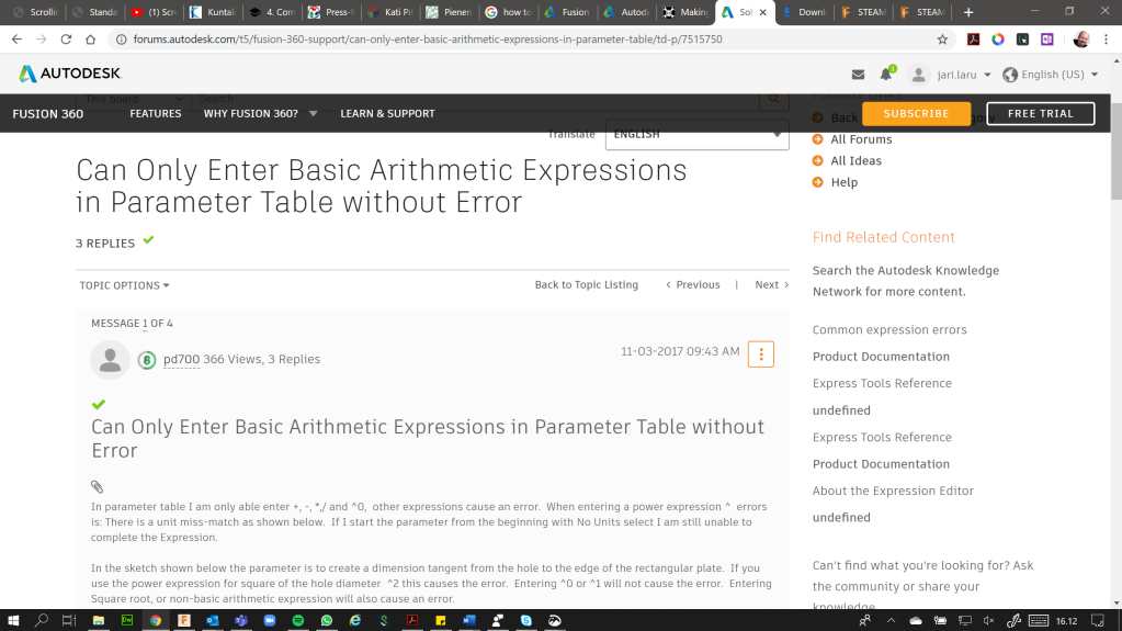
I got idea! Let's specify sides of the square by parameters! It helped me to keep form of the design as I hoped. Well, I got "parameters expression" failed warning. It was related to my special variable to specify width of the side and calculus which took account the kerf-size, widhth_of_the slot and..Anyway, it didn't work before I understood to remove millimeters from one of the paramemters. I used some forum discussion to get knowlegde about the issue, and I even understood something about it :)
But honestly speaking, this issue was yet solvable. Later on my model did "collapse" after midnight
Design where I have circle inside, first steps towards nightmare
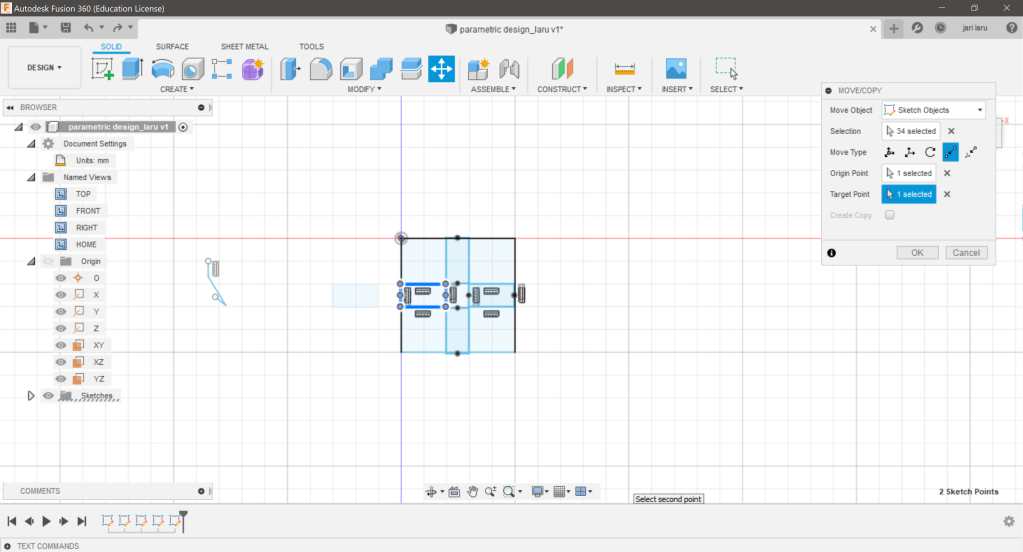
Of course I wanted to make my design more appealing and beautiful. I wanted to create design where I have circle inside of it and then slots added so, that also center of the block can be used to attach another slot
I thought that it would be easy, but I didn't remember to use tools for symmetric design, instead I tried to use constrains to help me with design. I got lost.
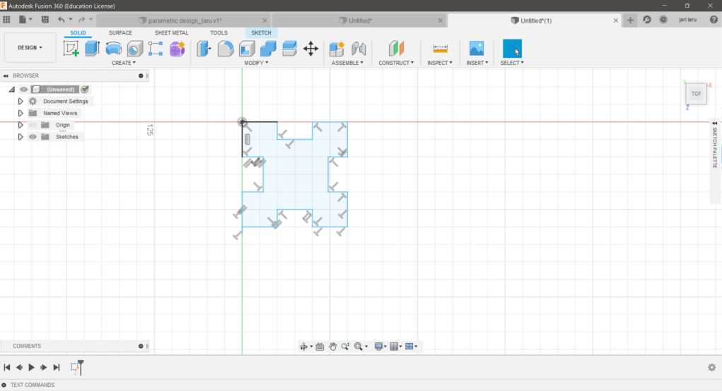
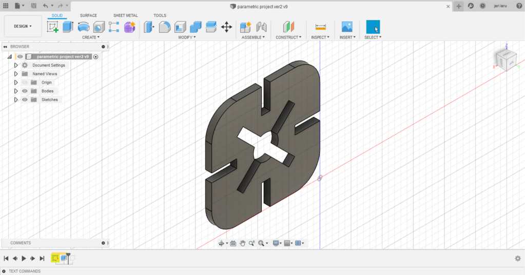
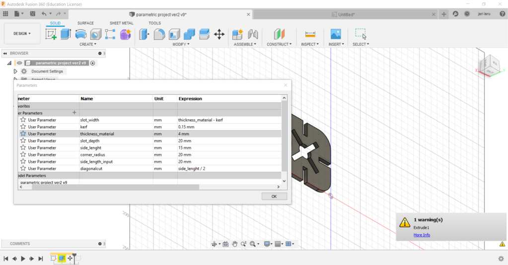
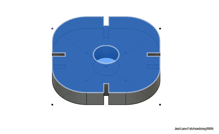
However, before I did realize that I did got lost, I was able to design quite beautiful object. Pity, that it didn't keep it's form when parameters were changed and also I got a lot of errors and warning from Autodesk FUsion. Here is picture about extruded design
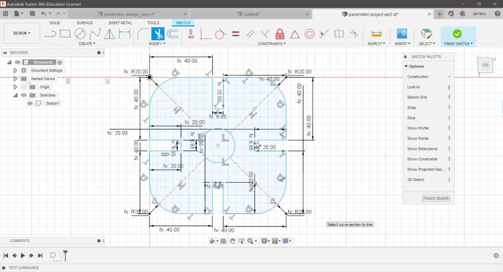
In that design phase I have already quite complex model with parameters and constrains.
Parameters explained (image below)
- slot_width: thickness of material - kerf. This parameter did work
- thickness of material: yep, like that
- slot_depth: depth of the slot (side slot)
- side_lenght: lenght of the side of the square
- corner radius: radius of the corner
- side_lenght_input: unused variable, was used in prevouis expressions, but was then removed
- diagonalcut: slot which starts from circle
- kerf: The laser burns away a portion of material when it cuts through. This is known as the laser kerf and ranges from 0.08mm – 1mm depending on the material type and other conditional factors (in this context it was 0.15mm
My final press-fit parametric design
I was so pissed of getting warnings and issues, that I finally deciced to simplify my drawing. Almost all issues came from circle and slots around it. So by simplifying the design I was able to complete this assignment
Parametric design for simple press-fit kit
In my last design I removed all complexities from the design. Workflow for sketching was as it follows (You can use any values for width etc, because in this step you just create sketc):
- Create > Rectangle > 2-point rectangle
- Keyboard L > Draw two lines from the opposite corner to opposite corner of the rectangle (right click on top of the line(s) to change lines to construction lines)
- Create > Circle > Center diameter Circle Draw circle in the crossing point of the construction lines)
- Create four squares (will be slots later on) or create one and copy rest of those to respective places in the middle of the square sides (Create > Rectangle > 2-point rectangle)
- Create slots by trimming the outer side of the four squares created above (press T to activate trim) and delete line to open slots
- Use fillet tool to create arcs in the corners of the square (modify > fillet)
HOX! You need to spesify values for sketch above by using parameters (Modify > Change parameters)
In the parameter dialog, you can found six fields (columns):
- Parameter: User parameters (user created parameters are under this label) and Model parameters
- Name: Expression which is actually is used to give name of the parameter
- Unit: Unit which is used for parameter (in my case mm)
- Expression: values or calculus (e.g. thickness - kerf)
- Value: parameter itself
- Comments: Optional comments
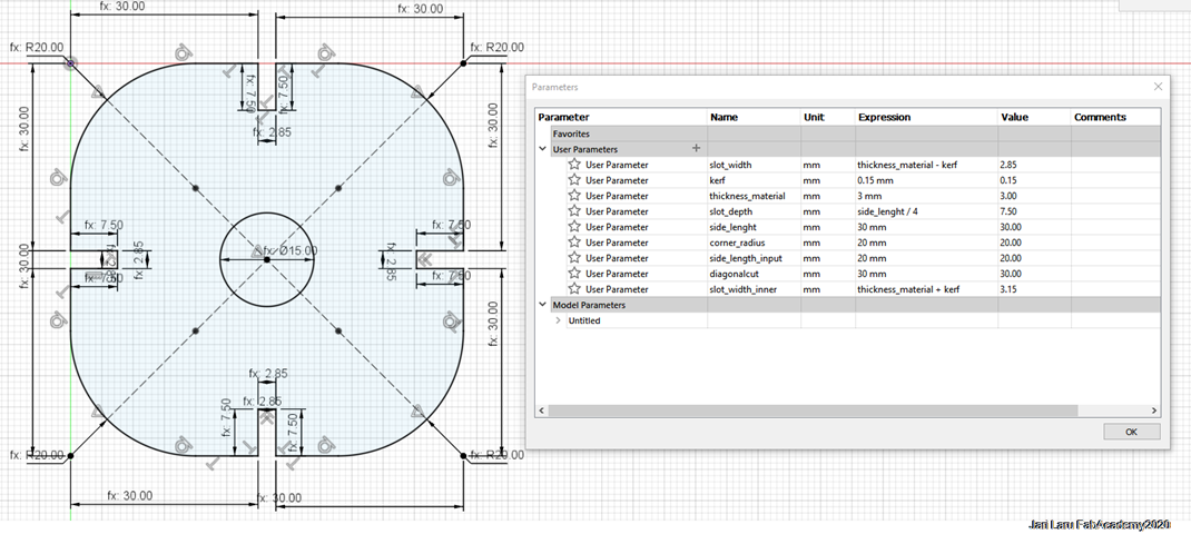
Parameters used in my design can be seen in the figure below. As you can see, all values in my simple sketch are controlled by parameters (fx = parameter used). So, for example, if I want to use for example, parameter to control "slot_width", I can just replace numerical value of the slot_width in the sketch with the parameter name.
Then close sketch mode and extrude sketch by pressing E key. You can use any value for extrude distance, because this phase is needed just for exporting PDF out from the Fusion 360 (lasercutting process is 2-dimensional)
Prepare your design for lasercutting
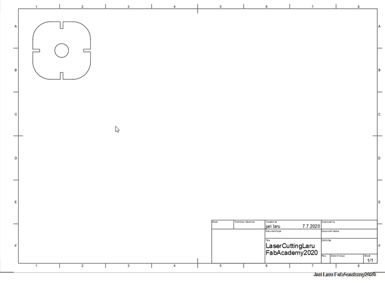
Then change mode from "Design" to "Drawing". This can be done just by clicking dialog on top-left corner of Fusion360.
Choose "drawing from design" when you open "Drawing" to start preparing export of the pdf-file for lasercutting
Only thing that you need to do, is to check that orientation of your design is correct (you can see your design on the "paper"). You can change orientation from "drawing view" -dialog (pop up menu on the right side of the view)
Then you can click "Output" button on the top toolbar and export your design in pdf-format.
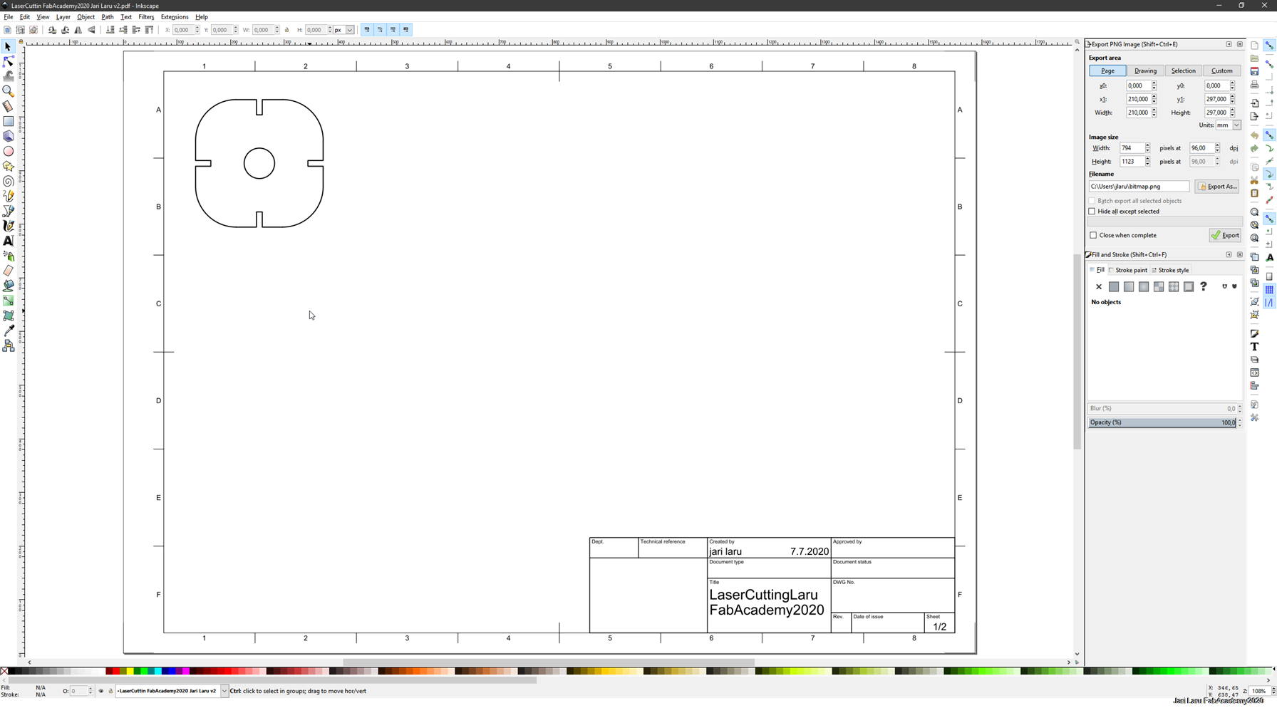
Next step is to open PDF in the Inkscape and do final preparations before lasercutting. Workflow is as it follows:
- Open the PDF (file > Open)
- Click OK to close dialog box shown during PDF import
- Check that your design is showing correctly and choose everything of it by mouse
- Ungroup all objects in your design to remove unnecesary parts of the document (sift-ctrl-g)
- Delete all other components from the screen except your own design (choose and delete)
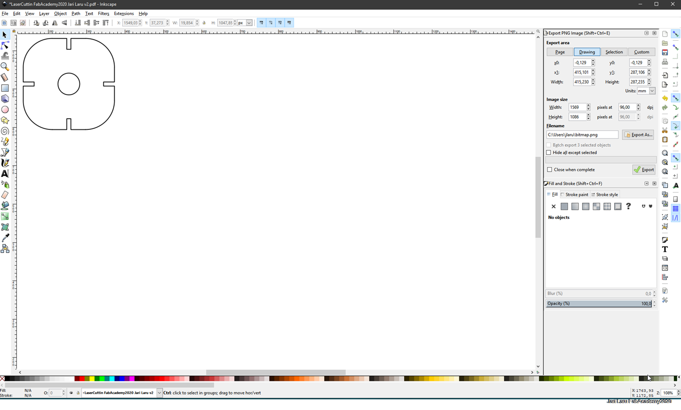
Next you need to decide how many fit-press objects you want cut. For example, I have copied my design now two times, so I have in total three objects to be cut.
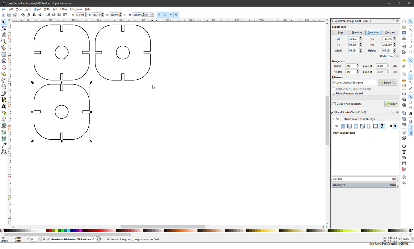
Last thing in Inkscape is to change stroke (line width) to 0.02mm (which is suitable for our Epilog laser cutter). Then you can export file into PDF or save into SVG (anyway you need to open your file the computer next to Epilog lasercutter)
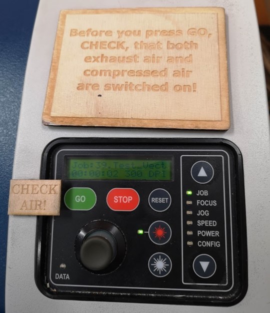
Lasercutting with Epilog M2 40
The machine operation starts from turning on switches for the energy and air-exhaust, and then the machine can be started with a power switch. To cut the pieces I used Epilog Fusion M2 40 Laser cutting machine with default settings for MDF 3 mm (Speed = 20%, Power = 100%, Frequency = 20%).
Steps of using lasercutter:
- The document was sent to print from the PDF file opened in Inkscape by simply Print or Ctrl+P combination.
- Using the joystick in the Jog mode move the laser to the start point of the cutter.
- Check the Focus adjusting the height with joystick and the calibrator (the tip of the calibrator should slightly touch the surface of the material).
- In the Job mode select the file and press Go.
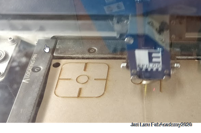
In the figure below you can see Epilog laser cutter cutting my first design. When this cut was ready, I noticed that I have to adjust my parametric design (slot was too narrow foo material)
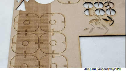
Here is the result after correct parameters. Final cut.
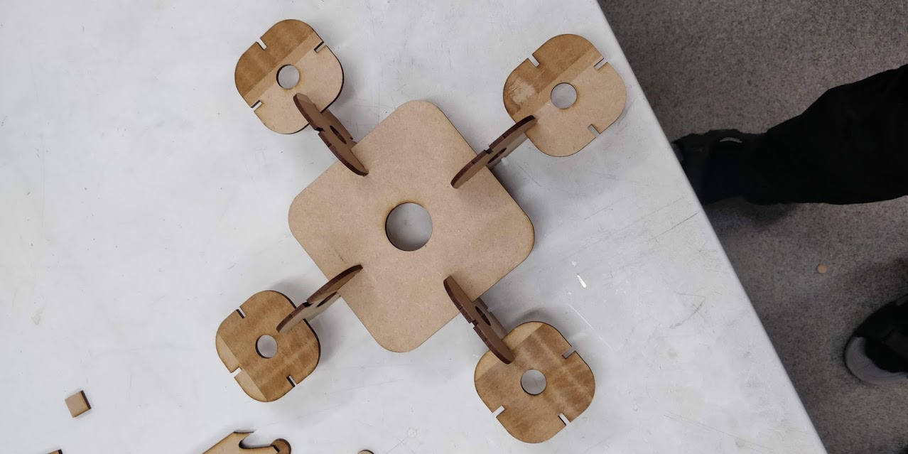
This is hero image, where I have used test cut from my earlier design as center (smaller parts are from the official final design)
Files
Vinyl Cutting
- SVG file (Scratch Cat, my vinyl cutting design)
Parametric Design
/inkspace_scratch.svg)
/inkscape_parametric_FIN.svg)